Sequence Diagram
Introduction to Sequence Diagrams
Sequence diagrams are a type of interaction diagram in UML (Unified Modeling Language) that illustrate how processes operate with one another and in what order. They are a powerful tool for visualizing the sequential logic of complex systems, particularly in software development and business process modeling.
Basic Definition
A sequence diagram shows object interactions arranged in time sequence. It depicts the objects and classes involved in the scenario and the sequence of messages exchanged between the objects needed to carry out the functionality of the scenario.
Key components of a sequence diagram include:
- Lifelines: Vertical dashed lines representing the existence of an object over time
- Messages: Horizontal arrows showing communication between objects
- Activation boxes: Rectangles on lifelines indicating when an object is active or performing an operation
Example of ZenUML Sequence Diagram:
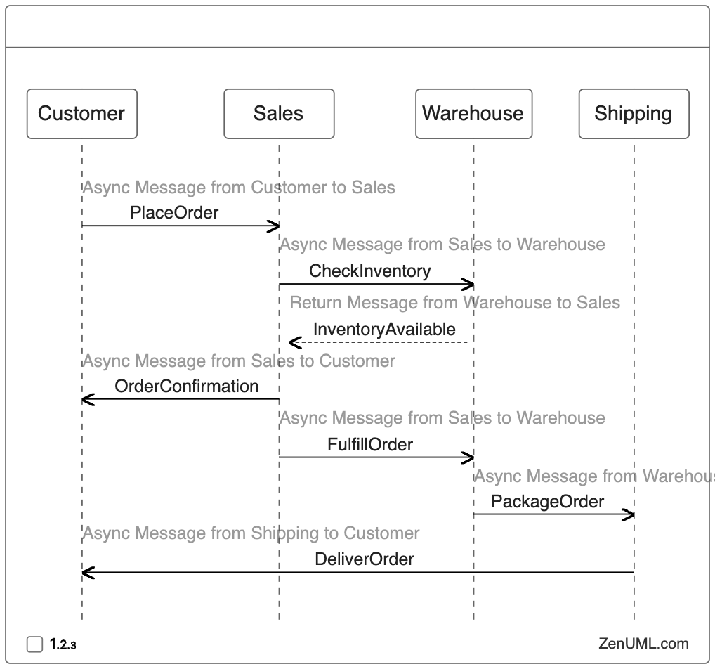
Live Code:
Best Practices for Creating Sequence Diagrams
To create effective and readable sequence diagrams, consider the following best practices:
-
Keep it simple: Focus on the essential interactions and avoid cluttering the diagram with unnecessary details.
-
Use clear naming conventions: Choose descriptive and consistent names for objects and messages.
-
Arrange objects logically: Place related objects near each other to minimize crossing lines.
-
Use appropriate message types: Distinguish between synchronous and asynchronous messages using different arrow styles.
-
Include time-order: Ensure messages flow from top to bottom to represent the correct sequence of events.
-
Add notes for clarity: Use text notes to explain complex interactions or provide additional context.
-
Consider using frames: Employ interaction frames to show alternative flows or iterations.
-
Maintain consistency: Ensure your sequence diagram aligns with other UML diagrams in your project.
Use Cases and Examples
Sequence diagrams are versatile and can be applied in various scenarios. Here are some common use cases:
-
Software Development Team Interaction
- Scenario: Visualizing collaboration and communication between team members during a project.
- Example: Developer → Code Review → Project Manager → Feedback → Developer
-
Business Process and Division of Labor
- Scenario: Mapping out the steps involved in a business workflow to clarify roles and responsibilities.
- Example: Customer → Order Placement → Sales Team → Processing → Shipping Department
-
Enterprise Architecture and Business Governance
- Scenario: Demonstrating the interactions between different departments to ensure compliance and governance.
- Example: Compliance Officer → Policy Review → Legal Department → Approval → Implementation Team
-
Business Transaction Process
- Scenario: Detailing the steps of a online transaction being processed.
- Example: Merchant → Acquirer → Payment Network → Bank → Confirmation
-
Mobile Application User Journey
- Scenario: Illustrating the flow of actions a user takes when using a mobile app.
- Example: User → App Launch → Login Screen → Dashboard → Content Interaction
-
Customer Support Interaction
- Scenario: Showcasing the communication process between a customer and support staff.
- Example: Customer → Support Ticket → Support Agent → Resolution → Customer Feedback
-
Software Deployment Pipeline
- Scenario: Visualizing the steps involved in deploying an application to production.
- Example: Developer → Code Commit → CI/CD Pipeline → Testing → Production Deployment
By using sequence diagrams in these scenarios, developers and stakeholders can gain a clear understanding of the system’s behavior, identify potential bottlenecks, and optimize the interaction flow between various components.